On Button Input Pressed
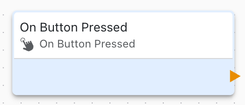
This block is triggered when a button or digital input is pressed (goes LOW to HIGH or HIGH to LOW, depending on configuration).
Overview
The On Button Input Pressed block detects button press events on GPIO digital input pins, enabling user input and sensor event detection.
Configuration
- GPIO Line: Which digital input pin to monitor
- Trigger Edge: Rising edge (LOW to HIGH) or falling edge (HIGH to LOW)
- Debounce: Debounce time in milliseconds
Button Wiring
Active HIGH (Pull-Down)
Button pressed: Pin goes from LOW to HIGH
GPIO Pin -> Button -> VCC
GPIO Pin -> Pull-down Resistor -> Ground
Trigger on: Rising edge
Active LOW (Pull-Up)
Button pressed: Pin goes from HIGH to LOW
GPIO Pin -> Button -> Ground
GPIO Pin -> Pull-up Resistor -> VCC
Trigger on: Falling edge
Debouncing
Debounce eliminates false triggers from:
- Mechanical button bounce
- Electrical noise
- Contact chatter
Typical debounce times:
- 10-50ms for mechanical buttons
- 5-10ms for electronic signals
- Adjust based on testing
Use Cases
Common button input scenarios:
User Control
On Button Pressed:
- Toggle light on/off
- Cycle through modes
- Start/stop process
- Confirm action
Sensor Detection
On Motion Sensor:
- Trigger alarm
- Turn on lights
- Log event

On Door Switch:
- Detect open/close
- Security monitoring
Industrial Inputs
On Limit Switch:
- Stop motor
- Detect position
- Safety interlock

On Emergency Stop:
- Immediate shutdown
- Lock out controls
Button Types
Momentary Buttons
- Pressed only while held
- Spring return
- Most common type
Toggle Switches
- Stays in position
- Two stable states
- Use for persistent state
Limit Switches
- Mechanical activation
- Position detection
- Safety applications
Input Configuration
Configure input pins:
- Pull-Up: Internal or external resistor to VCC
- Pull-Down: Internal or external resistor to ground
- Schmitt Trigger: Noise immunity
- Input Mode: Standard or interrupt
Multiple Buttons
Handle multiple buttons:
- Create separate blocks for each button
- Assign functions to each
- Implement button combinations
- Create button matrix (advanced)
Related Blocks
- On Button Released: Detect release event
- Digital Line Set: Control outputs
- Variable Set: Store button state
State Tracking
Track button state:
- Count presses
- Measure hold duration
- Detect double-click
- Implement long-press
Button Functions
Toggle
On Button Pressed:
    state = NOT state
    Digital Line Set: Output = state
Momentary Control
On Button Pressed:
    Digital Line Set: Output = HIGH
On Button Released:
    Digital Line Set: Output = LOW
Counter
On Button Pressed:
    count = count + 1
    If count >= 5:
        Trigger action
        count = 0
Long Press Detection
Detect long button press:
On Button Pressed:
    Start timer (3 seconds)

On Timer Complete:
    If button still pressed:
        Execute long-press action

On Button Released:
    Stop timer
    If timer not expired:
        Execute short-press action
Hardware Considerations
Pull Resistors
- Internal: 10-100kΩ (convenient)
- External: 4.7-10kΩ (more reliable)
- Choose based on noise environment
ESD Protection
- Buttons are user-accessible
- Add ESD protection diodes
- Use TVS diodes for sensitive inputs
Cable Length
- Long cables increase noise susceptibility
- Use shielded cable
- Add RC filter for debouncing
- Consider differential signaling
Safety Critical Inputs
For safety-critical buttons:
- Redundant input checking
- Fail-safe logic
- Hardwired safety circuits
- Regular testing
Interrupt vs Polling
Interrupt (Default)
- Immediate response
- Low CPU usage
- Best for time-critical
Polling
- Regular checking
- Simpler logic
- Higher CPU usage
Troubleshooting
Common button input issues:
- False triggers: Increase debounce time
- Missed presses: Decrease debounce or check wiring
- Inverted logic: Change trigger edge configuration
- Intermittent: Check connections and pull resistors
Best Practices
Button input best practices:
- Always use debouncing
- Proper pull resistors
- Test in noisy environment
- Document button functions
- Provide user feedback (LED, beep)
- Implement safety checks
- Consider accessibility
Advanced Features
Button Combinations
If (Button1 pressed AND Button2 pressed):
    Execute special function
Mode Selection
Press count 1: Mode A
Press count 2: Mode B
Press count 3: Mode C
Hold 3 seconds: Settings menu
Button Matrix
Multiple buttons with fewer pins (advanced)
Linking to Variables
Button state can link to variables:
- Automatic input variable created
- Read variable for current state
- Monitor state changes
- Log button events