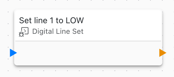
Digital Line Set
This block sets a GPIO digital line to HIGH or LOW. Use it to control digital outputs like relays, LEDs, and motors.

Overview
The Digital Line Set block controls GPIO (General Purpose Input/Output) digital output pins, enabling direct hardware control for relays, indicators, and actuators.
Configuration
- GPIO Line: Which digital pin to control
- State: HIGH (1) or LOW (0)
Use Cases
Common digital output scenarios:
Relay Control
Control AC/DC loads:
Turn ON pump: Digital Line Set = HIGH
Turn OFF pump: Digital Line Set = LOW
LED Indicators
Show device status:
Status OK: Green LED = HIGH, Red LED = LOW
Status Error: Green LED = LOW, Red LED = HIGH
Motor Control
Control DC motors:
Motor Forward: Pin A = HIGH, Pin B = LOW
Motor Reverse: Pin A = LOW, Pin B = HIGH
Motor Stop: Pin A = LOW, Pin B = LOW
Solenoid Valves
Control fluid flow:
Valve Open: Solenoid = HIGH
Valve Closed: Solenoid = LOW
GPIO Configuration
Configure GPIO lines:
- Output Mode: Push-pull or open-drain
- Initial State: State at power-on
- Pull Resistor: Internal pull-up/pull-down
- Drive Strength: Current capability
Dynamic Control
Set state dynamically:
- Use variables for state
- Calculate state from conditions
- Control based on sensor readings
- Implement logic patterns
Timing
Control timing:
- Instant on/off switching
- Debounce delays
Multiple Outputs
Control multiple pins:
- Create separate blocks for each pin
- Coordinate multiple outputs
- Implement sequences
- Parallel control
State Persistence
Remember output state:
- Save state to settings
- Restore on reboot
- Default state on startup
- Power-fail safety
Related Blocks
- On Button Pressed: Detect button input
- On Button Released: Detect button release
- Variable Set: Use variables to control state
Linking to Variables
Link GPIO to variables:
- Automatic hardware variable created
- Set variable to control output
- Variable shows current state
- Bidirectional synchronization
Applications
Home Automation
Light Control: GPIO -> Relay -> Light
Lock Control: GPIO -> Solenoid -> Door Lock
Fan Control: GPIO -> Relay -> Fan
Industrial Control
Pump Control: GPIO -> Contactor -> Pump Motor
Valve Control: GPIO -> Solenoid -> Pneumatic Valve
Alarm: GPIO -> Horn/Beacon
Robotics
Motor Driver: GPIO -> H-Bridge -> DC Motor
Servo Enable: GPIO -> Servo Controller
Gripper: GPIO -> Solenoid -> Pneumatic Gripper
Safety Considerations
Implement safety features:
- Watchdog timeout to safe state
- Emergency stop input
- Interlock logic
- Fail-safe defaults
Sequences
Implement output sequences:
1. Digital Line Set: Valve 1 = HIGH (open)
2. Delay 2 seconds
3. Digital Line Set: Pump = HIGH (on)
4. Wait for level sensor
5. Digital Line Set: Pump = LOW (off)
6. Delay 1 second
7. Digital Line Set: Valve 1 = LOW (close)
Troubleshooting
Common GPIO output issues:
- Output not working: Check wiring and pin configuration
- Insufficient current: Use external driver/relay
- Wrong voltage: Verify logic levels
- Flickering: Check power supply and connections
Best Practices
GPIO control best practices:
- Document pin assignments
- Implement safety interlocks
- Use appropriate drivers for loads
- Add protection circuits
- Test emergency stop
- Initialize to safe state
- Monitor output status
Hardware Examples
Control Relay Module
GPIO Pin -> Relay Module Input
Relay Common -> Load Hot Wire
Relay NO -> Load Return
Control LED
GPIO Pin -> 330Ω Resistor -> LED Anode -> Cathode -> Ground
Control DC Motor (via transistor)
GPIO Pin -> Base Resistor -> NPN Transistor -> Motor -> Power Supply