TPS2
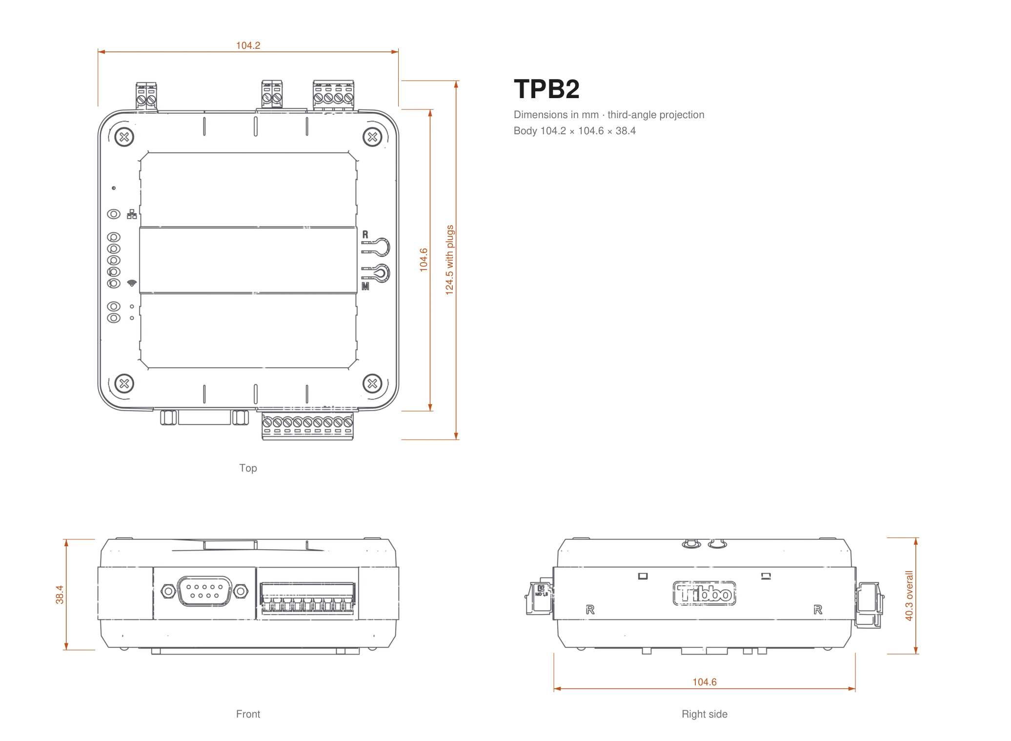
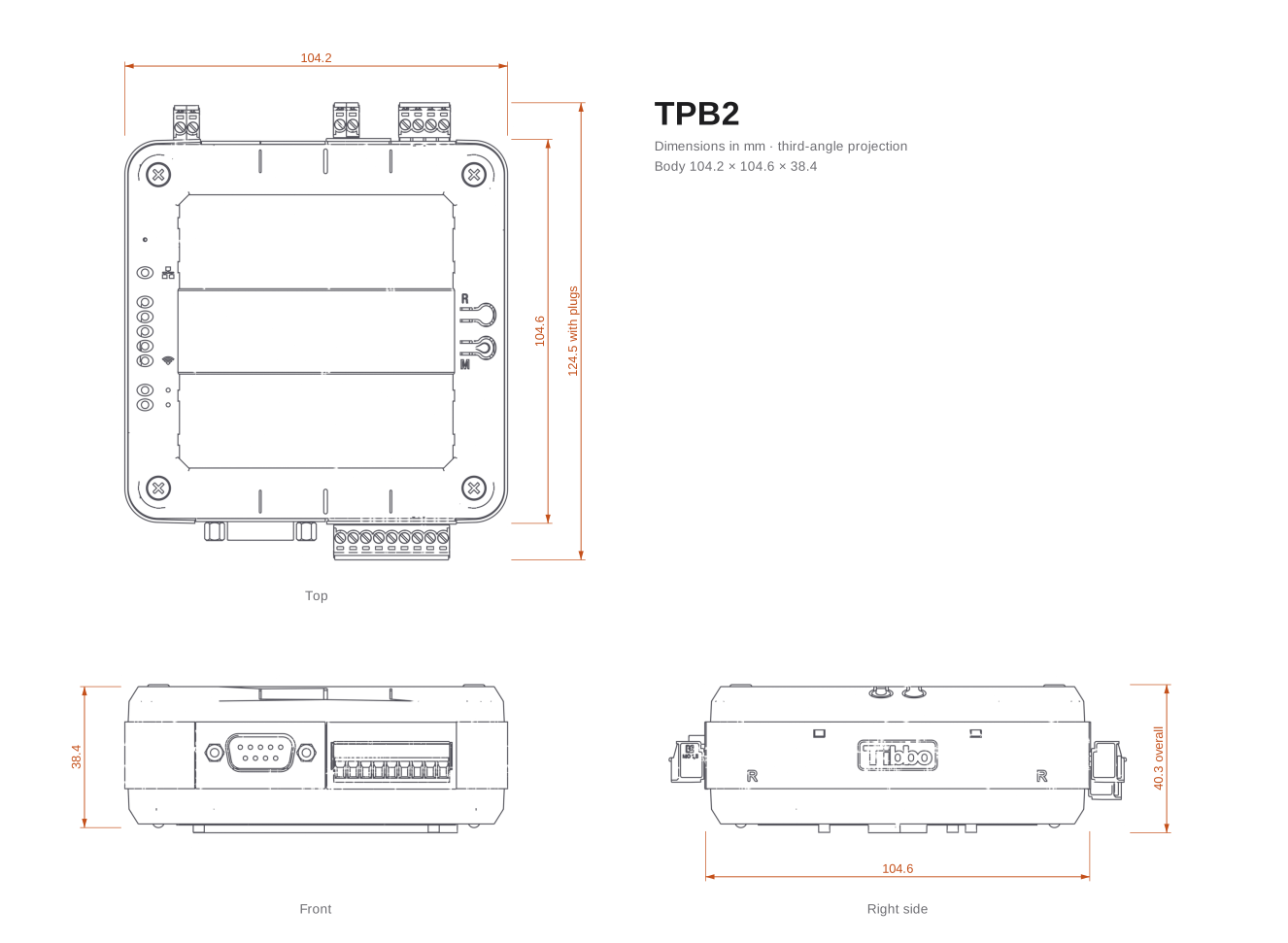
Compact, with status LEDs and a label window.
TPB2 enclosure
Tibbo Project System
Pick the box, with or without a screen, plug in the I/O you need, and program it in AppBlocks. The same Tibbits fit every model.
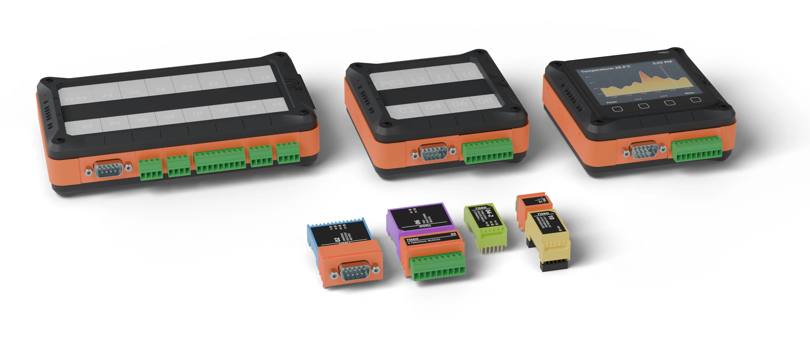
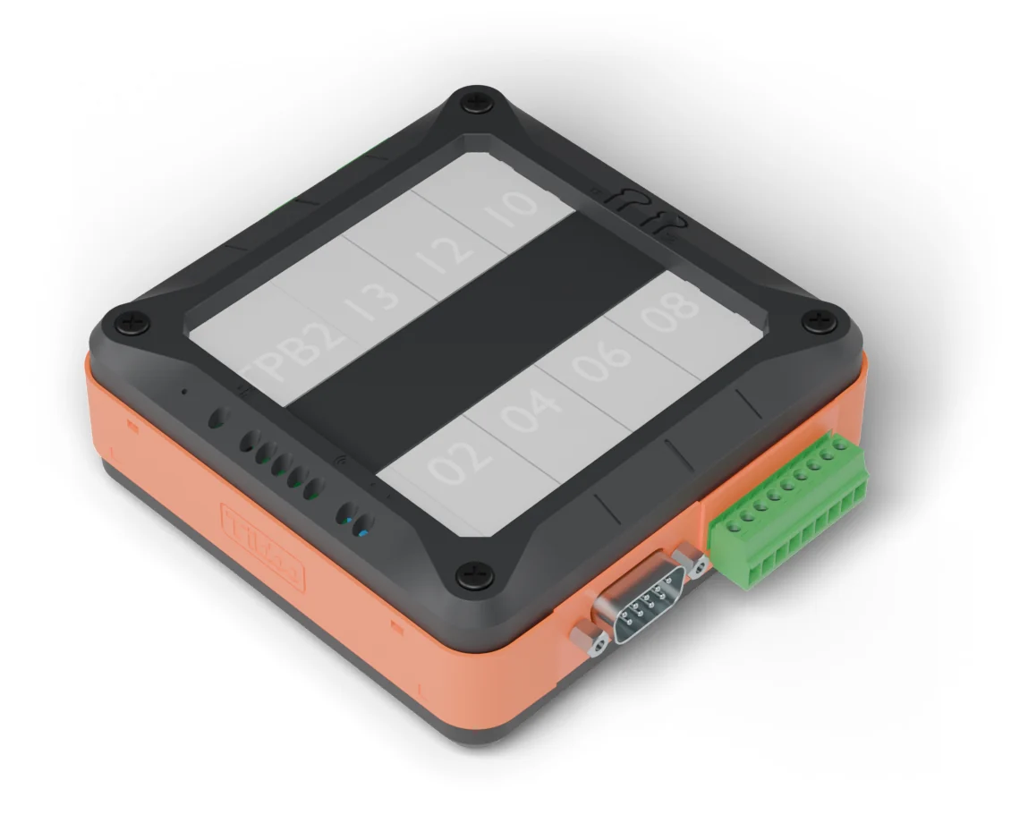
Compact, with status LEDs and a label window.
TPB2 enclosure
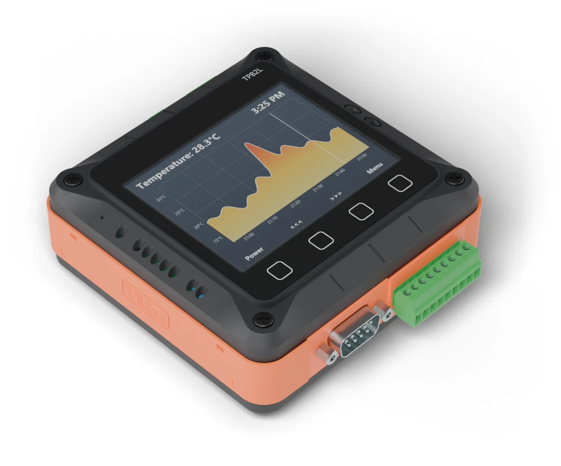
The same size, with a colour LCD and a sensor keypad.
TPB2L enclosure
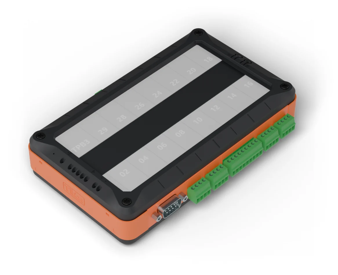
Twice the sockets, for bigger I/O counts.
TPB3 enclosure
A top cover with the screen and keypad, a vibration plate, the board with your Tibbits, side walls and a base. Scroll to take one apart.
Each Tibbit is a module, with a connector where it needs one, that plugs into a socket. Choose the ones the job needs.
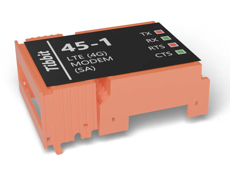
For sites with no cable to run.
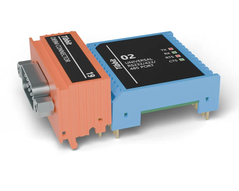
Modbus RTU meters, drives and older equipment.
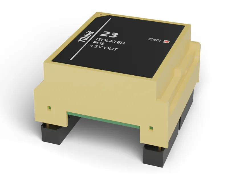
Power and network over one Ethernet cable.
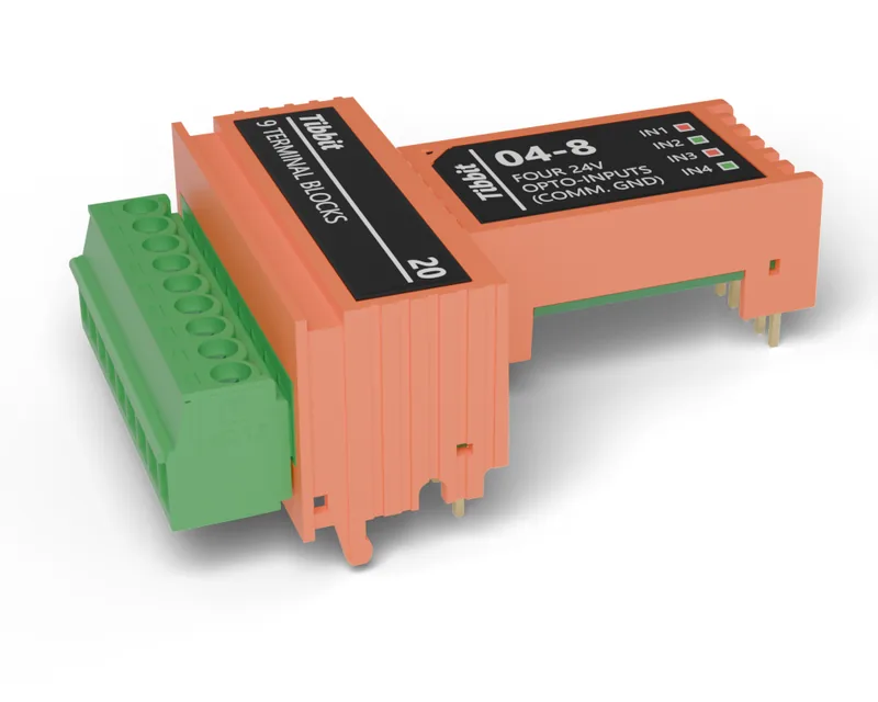
Switches, sensors and contacts, isolated from the field.
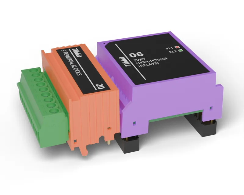
Switch pumps, valves and contactors.
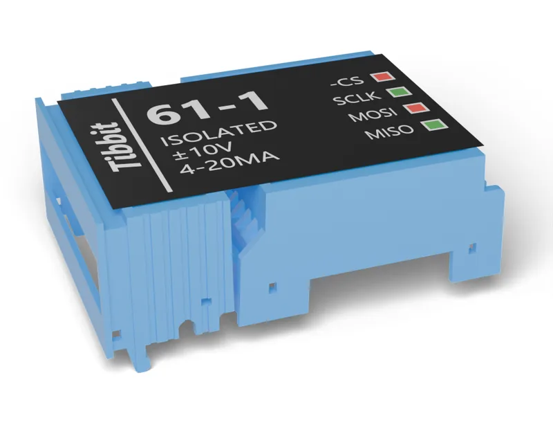
Transmitters for level, pressure and flow.
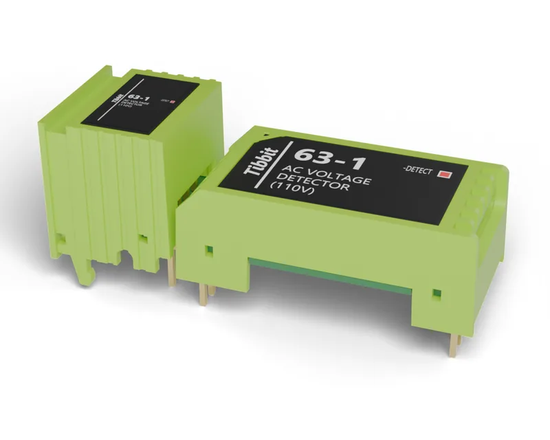
See whether mains is present, and switch it.
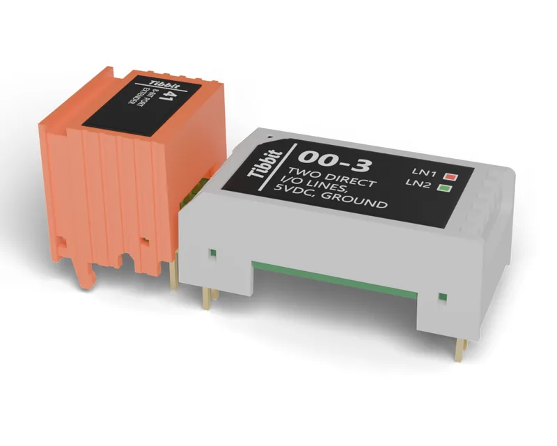
Eight digital lines on a cable, wherever they’re needed.
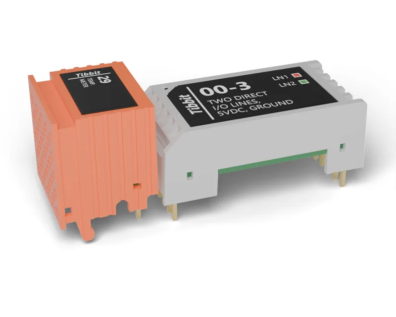
Measure the box’s surroundings directly.
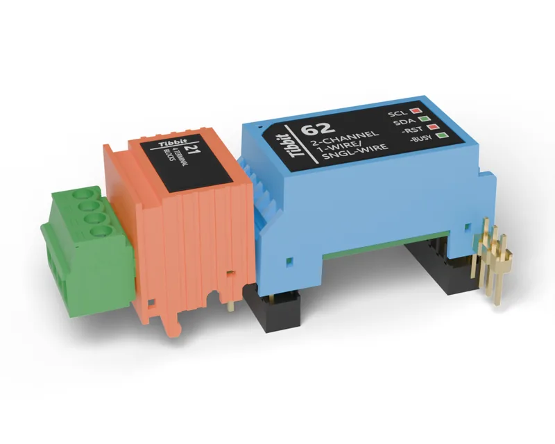
Temperature probes and other bus sensors.
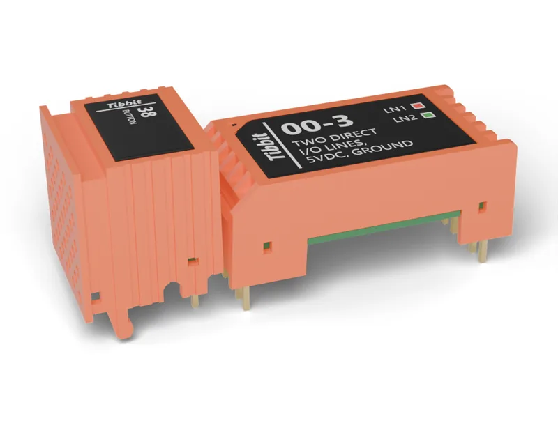
A push button on the box itself.
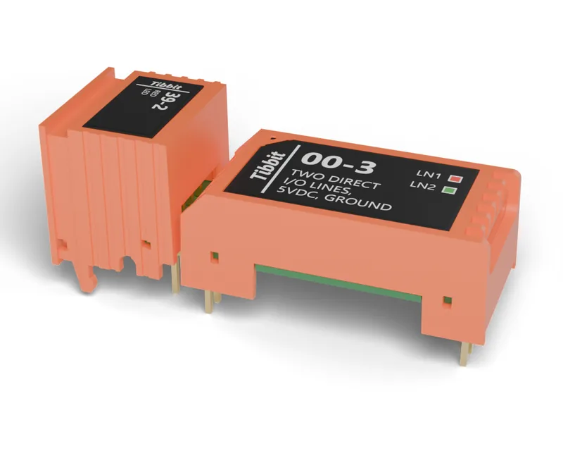
Status you can see across the room.
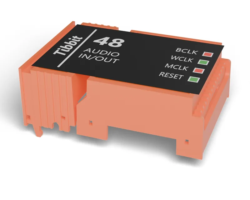
Sound in and out: announcements, alarms, intercom.
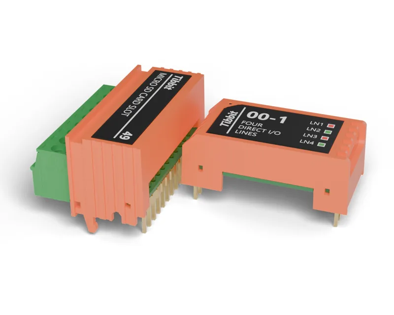
Log data locally, keep files on the device.
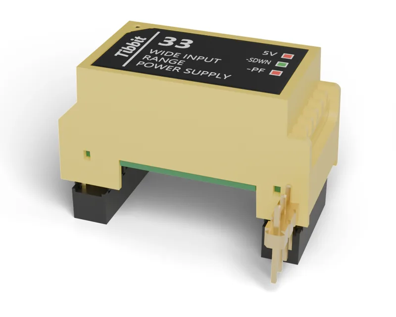
Run it from 12, 24 or 48 V. Each supply takes its input through the connector beside it.
| TPS2 | TPS2L | TPS3 | |
|---|---|---|---|
| Hardware | |||
| Controller board | TPP2 | TPP2 | TPP3 |
| Tibbit sockets | 12 (6 module, 6 connector) | 12 (6 module, 6 connector) | 28 (14 module, 14 connector) |
| Serial ports (UART sockets) | Up to 4 | ||
| Display | Status LEDs, paper label window | 3.5" colour LCD, 4-key keypad | Paper label window |
| Size and mounting | |||
| Body (W × D × H) | 105 × 105 × 39 mm | 105 × 105 × 42 mm | 176 × 105 × 39 mm |
| Mounting | 35 mm DIN rail (EN 60715) or flat | ||
| Power | |||
| On the board | Regulated 5 V terminal | ||
| With a power Tibbit | 9–18 V (#09, #10), 8–60 V (#25, #33), PoE (#23) | ||
| Power input | A #18 jack and terminals (or a terminal block) in the socket beside the supply | ||
| Connectivity | |||
| Ethernet | RJ45 | ||
| Wi-Fi | Optional add-on (WA2000) | ||
| Bluetooth | Optional add-on (WA2000) | ||
| Field I/O | Through Tibbits: RS232/422/485, relays, isolated inputs, ADC/DAC and more | ||
| Software | |||
| Programming | AppBlocks in the browser; Tibbo BASIC/C in TIDE | ||
| Fleet | AppBlocks Cloud: device groups, OTA updates | ||
| Environment and approvals | |||
| Operating temperature | 40 ~ +70°C | 40 ~ +70°C | 40 ~ +70°C |
| Certifications | CE, FCC, RoHS | CE, FCC, RoHS | CE, FCC, RoHS |
Choose the board, drop Tibbits into its sockets and AppBlocks checks the layout and the power budget.
Start building free