
5 posts tagged with "lcd"

View All Tags

BP Sensors to LCD Graph

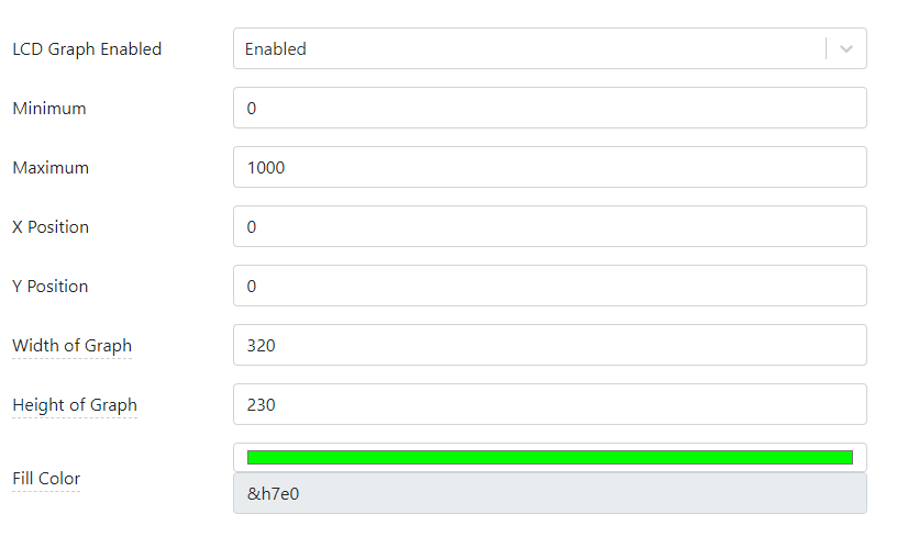
AppBlocks has the facility to draw a chart on the TPS2L's LCD. This is enabled on the LCD Graphing page of the Features Tab. You can select the graph's scale, position on the screen, color, and other parameters:

bpsensortolcdgraph

LCD graphing is only available for projects using the TPP2(G2) platform. This is because only this platform offers the LCD option. Since using this facility requires an LCD, it has to be enabled on the hardware configuration page:

bpsensortolcdgraph

The actual charting is performed using the LCD Graph block. Every time this block is executed, a value of your project's variable selected in the block's properties is shown as the next data point on the graph.

Connecting a Bus Probe (BP) Sensor

Bus Probes (BPs) are a line of RS485 Modbus sensors manufactured by Tibbo Technology. This project shows how to receive the data from the BP#03 sensor, which measures the ambient light. The data from the sensor is then charted on the TPS2L's LCD.

Our AppBlocks Demo Kit (ADK) is equipped with the BP#02 and BP#03 sensors, so the Kit owners will be able to run the application immediately. If you don't have the ADK, here is how you connect a BP sensor to a TPS device.

To communicate with Modbus sensors, your TPS must have an RS485 Tibbit. In this project, we used Tibbit#05. Tibbit #05 not only implements the RS485 port but also breaks out the ground and +5V power lines of the TPS system. Since BP sensors can run on 5V power, this Tibbit is all you need to connect the sensors to your TPS. Here is the wiring diagram for attaching a BP sensor to the TPS. All sensors in the BP lineup have identical wiring requirements:

ac_not_found

Modbus Configuration in the Application

To work with BP sensors and most other Modbus devices, an application must be configured as a Modbus master. This is done on the Modbus Master page of the Features Tab:

bpsensortolcdgraph

As you can see, the Device ID of the sensor is 66. This is an arbitrary choice -- the ID may be different, but the BP sensor must be assigned a matching ID for the system to work. To configure your BP sensor, use the WebBP web app from Tibbo. You will need a Web485 Board and a Chrome (or Chromium-based) browser to use the app. BP sensors installed on the AppBlocks Demo Kit come pre-configured with IDs matching those expected by the Tutorial applications.

In addition to the ID configuration, you must add all Modbus registers you want your TPS to poll. BP03 has a single register of interest:

bpsensortolcdgraph

Once you add a Modbus register, a linked variable is auto-generated. This is similar to the automatic creation of variables for (one-shot) timers, settings, and IO lines:

bpsensortolcdgraph

Modbus Polling

AppBlocks handles all Modbus polling in the background. All your application has to do is read the linked variable's value. Click on the LCD Graph block on the canvas to see that it contains a single property for selecting a variable, the light variable in this case. This is the auto-generated variable linked to the BP sensor's register.

bpsensortolcdgraph

Run this application to see the graph appear on the TPS LCD.

You can connect a wide variety of Modbus devices to your TPS, so the choice is not limited to Modbus products offered by Tibbo alone. AppBlocks also supports Modbus TCP, allowing you to work with "networked" Modbus slaves. Your TPS itself can serve as a Modbus slave device. This is configured on the Modbus Slave page of the Features tab.

Sprinkler Control 3: Status on LCD

This project expands on the previous application by adding status messages displayed on the LCD. For this to work, you must have the TPS2L(G2) device -- only this model has the LCD (and keypad).

LCD messages are printed using the LCD Print block. The application prints two messages: "WATERING (SPRINKLERS ON)" and "IDLE". Click on either block to see the list of available properties:

sprinkler_lcd_print

LCD messages are printed within the bounds of a rectangle formed by the X Position, Y Position, Width, and Height parameters. The Text Alignment property defines the text alignment within this rectangle, while Text Orientation allows you to print the text normally, upside down, or vertically.

sprinkler_lcd_print

For example, to print the "IDLE" message in the middle of the screen, use X Position = 0, Y Position = 0, Width = 320, Height = 240, and Text Alignment = Middle Center.

The numbers 320 and 240 come from the TPS screen resolution, which is 320 x 240 pixels.

Sprinkler Control 4: Manual Watering

It is great to have the watering happen on schedule, but sometimes you will want to manually operate the sprinklers, even if to test that the hardware works properly.

This Sprinkler Control project step adds a manual override: The TPS2L(G2) has a four-key keycap. The application displays "ON" over the first key (F2) and "OFF" over the fourth key (F4). Pressing the "ON" key turns the relay on, and the "WATERING (MANUAL)" message is shown on the screen. Pressing the "OFF" key turns the relay off.

The response to key presses is implemented through the On Keypad Pressed event block (the corresponding key is selected in the block's properties).

There is also the On Keypad Released event block.

Explore how this application implements overrides. This is done correctly: Once you have enabled the sprinklers manually, the end of scheduled watering will not turn the relay off. This logic is implemented through the manual_override variable.

Sprinkler Control 5: Web Dashboard

In this next iteration of the Sprinkler Control project, the ability to monitor the state of and control the sprinkler relay remotely is added. This is done through the dashboard, a page of your device's web interface that can host widgets. The dashboard is configured on the General subpage of the Web Dashboard page of the Features tab. Open this page to see the widget this project uses:

sprinkler_widgets

The widget is of the Switch type. The switch is "connected" to the manual_override variable:

sprinkler_dashboard_variable

This "connection" is bi-directional:

  • If you push the "ON" or "OFF" button on the TPS, the dashboard switch will reflect the current manual_override state.
  • If you flip the switch on the dashboard, the manual_override variable will be updated.
sprinkler_control_5

To react to the dashboard switch flips, an On Variable Changed event block has been added to the application. This event triggers when the corresponding variable value changes.

The On Variable Changed block was first introduced in the Settings project.

This, and many other projects, takes advantage of the LUIS interface. The application makes two settings -- Ethernet DHCP and Ethernet IP -- accessible from the LUIS smartphone app.

Sprinkler Control 6: Multiple Zones

In the final version of the Sprinkler Control project, we go multi-zone. The application only controls two relays (to save the slot space inside your TPS), but you can easily extend it to individually control many more watering zones.

The first step in adding the multi-zone support was to add the sprinkler_num field to the sprinkler_schedule table. Notice how the field's Minimum and Maximum properties come in handy here: the minimum sprinkler number is 1, and the maximum is 2:

sprinkler_table_config_2

The second step was adding the For-Next Loop block to the diagram. This is the first project where we do "loops." Click on the For-Next Loop block to open its properties. As you can see, the block iterates from 0 to 1 (inclusive). The block runs twice, first, with the value of 0, and second, with the value of 1.

sprinkler_for

When a block chain is connected to the Iterate output of the For-Next Loop block, this entire chain runs once for each for-next loop. This means the application will perform the Table Lookup and everything behind it twice.

sprinkler_table_lookup

Record Offsets

Now it is time to look inside the Table Lookup block. The element interesting to us right now is the Record Offset property. The current_iteration parameter of the For-Next Block is there. The Table Lookup will first run with the Record Offset of zero and then with the Record Offset of one.

When at zero, the Record Offset instructs the Table Lookup block to search from the beginning of the table and find the first data table record matching the search criteria. Setting the Record Offset to one will make the Table Lookup block search for the second record matching the search criteria.

If you fix the record offset at zero, this application won't work correctly when both sprinkler relays are to be activated simultaneously. The following example illustrates why. Let's say that you have this watering schedule:

sprinkler_numwatering_timeduration
108:00 AM300
208:30 AM300
106:00 PM600
206:00 PM600

At 08:00 AM, the first record will be fetched. At 08:30 AM, the second record will be fetched. Now, what will happen at 06:00 PM? At the first for-next loop iteration, the third record will be fetched. When the loop runs for the second time, the same third record will be fetched again -- that is, if the Record Offset parameter is always at 0. If this parameter is set to match current_iteration, then the first matching record (the third record) will be ignored, and the second matching record (the fourth record) will be found!

This, and many other projects, takes advantage of the LUIS interface. The application makes two settings -- Ethernet DHCP and Ethernet IP -- accessible from the LUIS smartphone app.

Monitoring the Sprinkler Relay State

On the AppBlocks Demo Kit (ADK), the first "sprinkler" relay is connected to the green LED marked "RL1." The second "sprinkler" relay is connected to the red LED "RL2." Either LED is on when the corresponding relay is on.