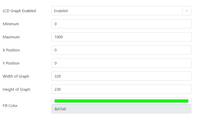
AppBlocks has the facility to draw a chart on the TPS2L's LCD. This is enabled on the LCD Graphing page of the Features Tab. You can select the graph's scale, position on the screen, color, and other parameters:
LCD graphing is only available for projects using the TPP2(G2) platform. This is because only this platform offers the LCD option. Since using this facility requires an LCD, it has to be enabled on the hardware configuration page:

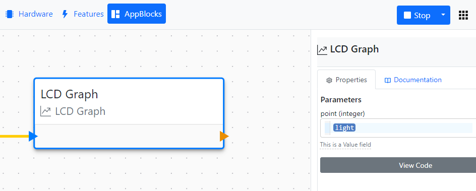
The actual charting is performed using the LCD Graph block. Every time this block is executed, a value of your project's variable selected in the block's properties is shown as the next data point on the graph.
Connecting a Bus Probe (BP) Sensor
Bus Probes (BPs) are a line of RS485 Modbus sensors manufactured by Tibbo Technology. This project shows how to receive the data from the BP#03 sensor, which measures the ambient light. The data from the sensor is then charted on the TPS2L's LCD.
Our AppBlocks Demo Kit (ADK) is equipped with the BP#02 and BP#03 sensors, so the Kit owners will be able to run the application immediately. If you don't have the ADK, here is how you connect a BP sensor to a TPS device.
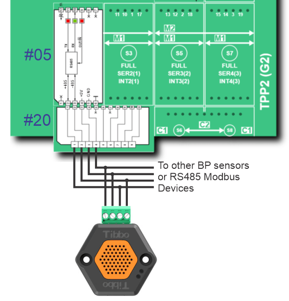
To communicate with Modbus sensors, your TPS must have an RS485 Tibbit. In this project, we used Tibbit#05. Tibbit #05 not only implements the RS485 port but also breaks out the ground and +5V power lines of the TPS system. Since BP sensors can run on 5V power, this Tibbit is all you need to connect the sensors to your TPS. Here is the wiring diagram for attaching a BP sensor to the TPS. All sensors in the BP lineup have identical wiring requirements:
Modbus Configuration in the Application
To work with BP sensors and most other Modbus devices, an application must be configured as a Modbus master. This is done on the Modbus Master page of the Features Tab:
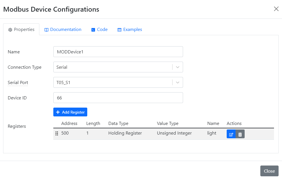
As you can see, the Device ID of the sensor is 66. This is an arbitrary choice -- the ID may be different, but the BP sensor must be assigned a matching ID for the system to work. To configure your BP sensor, use the WebBP web app from Tibbo. You will need a Web485 Board and a Chrome (or Chromium-based) browser to use the app. BP sensors installed on the AppBlocks Demo Kit come pre-configured with IDs matching those expected by the Tutorial applications.
In addition to the ID configuration, you must add all Modbus registers you want your TPS to poll. BP03 has a single register of interest:

Once you add a Modbus register, a linked variable is auto-generated. This is similar to the automatic creation of variables for (one-shot) timers, settings, and IO lines:

Modbus Polling
AppBlocks handles all Modbus polling in the background. All your application has to do is read the linked variable's value. Click on the LCD Graph block on the canvas to see that it contains a single property for selecting a variable, the light variable in this case. This is the auto-generated variable linked to the BP sensor's register.
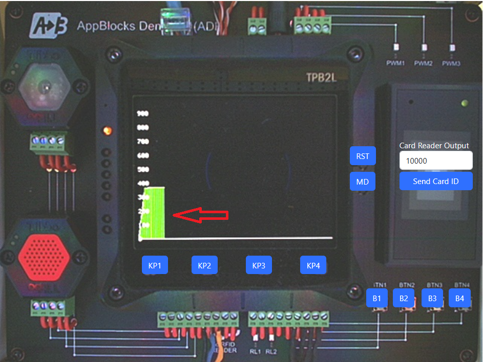
Run this application to see the graph appear on the TPS LCD.
If you are working with a physical ADK, you can easily cause changes in sensor measurements: Cover the light sensor's window or shine a light into the same to cause changes in measured ambient light.
There is no way to influence the environment of Cloud ADK sensors, and their output remains virtually constant.
You can connect a wide variety of Modbus devices to your TPS, so the choice is not limited to Modbus products offered by Tibbo alone. AppBlocks also supports Modbus TCP, allowing you to work with "networked" Modbus slaves. Your TPS itself can serve as a Modbus slave device. This is configured on the Modbus Slave page of the Features tab.