This topic opens a new series of projects that show you how to build an access control system. The first iteration is simple: Users present their ID cards, and the system unlocks the door for the users whose cards are in the data table.
Most card readers on the market have the so-called Wiegand interface, and Tibbo offers a special Tibbit -- #08 -- to interface with Weigand readers. Our AppBlocks Demo Kit (ADK) comes equipped with such a reader, as well as all other inputs and outputs required for testing all projects in the Access Control chapter.
All projects in this series can also be tested on CloudADKs. Since it is not possible to bring ID cards to a reader on a Cloud Kit, the CloudADK panel provides a text field for entering reader data and a button to send this string into the Wiegand port of the TPS.
Wiring in a Wiegand Reader
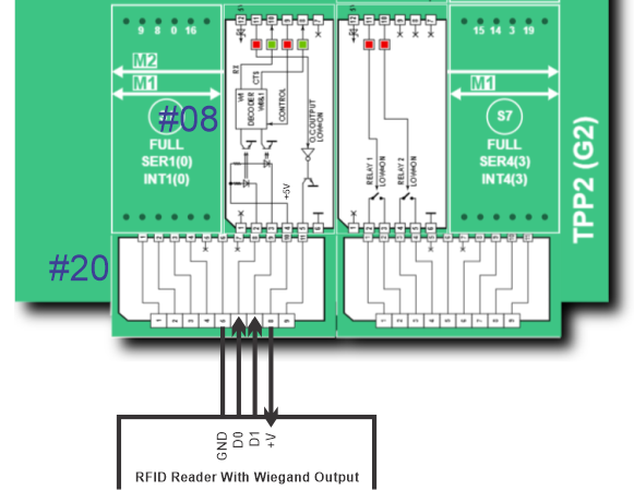
Here is the connection diagram for wiring a typical reader to Tibbit #08. In this diagram, the +5V power comes from your TPS. This is possible only if your reader can run on 5V power:
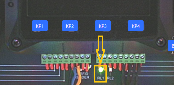
The electric door lock is controlled using a mechanical relay. You already saw the use of such a relay in the Scheduler (Sunrise & Sunset) project, as well as the Sprinkler Control chapter. In the ADK, this relay is connected to a green LED marked "RL1." The LED is on when the relay is on.
This and other LEDs of the Kit are also visible on CloudADKs.
The key block for working with Wiegand readers is the On Wiegand event block. It outputs the card's ID code as a string consisting of zeroes and ones.
Wiegand cards have a pre-defined format. A standard 26-bit Wiegand card allocates 8 bits (two hexadecimal characters) for the facility code, 16 bits (four hex characters) for user IDs, and two bits for parity checks. There are other Wiegand data lengths in circulation. Unless your customer actually pays attention to these Wiegand "conventions," it is entirely up to you how to interpret the Wiegand data. The simplest way is to view the entire code as the ID code. This is what we did in this project series.
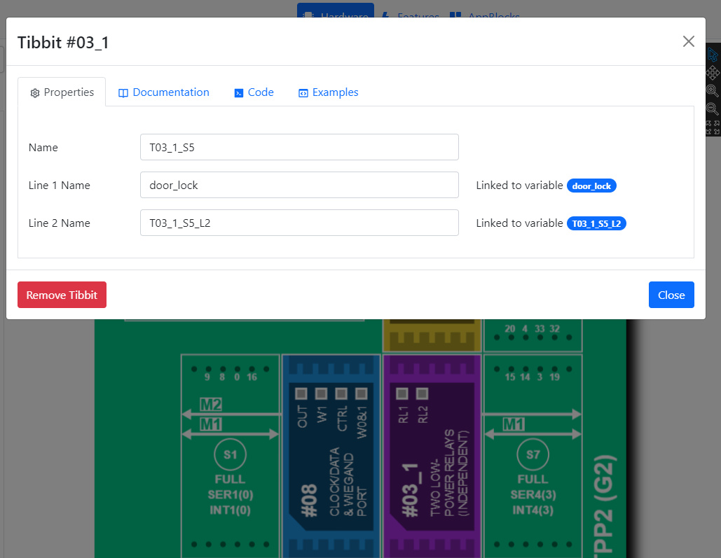
User IDs are stored in the user_id table containing a single field -- the card_id. When the user presents an ID card, the card code is compared against the user_id table records. This happens in the Table Lookup block. The door_lock variable is set to 0 if a matching record is found. This is an auto-generated variable linked to the IO line controlling the door lock relay:
If you are working with a physical Kit (TPS+reader), you'll need to know the ID codes of your cards before you can add them to the data table. For this reason, ID codes are echoed in the console every time you read the cards. You will notice that all codes appear in hexadecimal form.
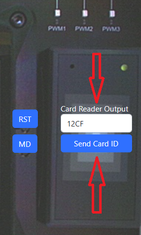
Cloud ADKs allow you to emulate the reader output. To do so, enter a string of up to six hexadecimal characters into the Card Reader Output textbox and press Send Card ID. Since the codes are under your control, you can enter them directly into the data table.
The project has three settings. Two of those are the customary Ethernet DHCP and Ethernet IP settings. The third one is the lock_activation_duration setting. Every time the door is unlocked, the _lock_activation_tmr timer is loaded with the value of this setting. Once the timer counts to zero, the relay is turned off.
Setting and data table editing is performed via your device's web interface.
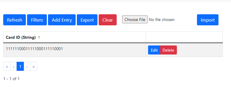
Forgot how to access the web interface (console) of a physical ADK or a Cloud Kit? See the Settings project.
Reading a valid card activates the door relay for the lock_activation_duration number of seconds. On the ADK, this relay is connected to a green LED marked "RL1."
This LED is visible in the virtual panel of CloudADK Kits as well.