This final step shows you how to work with real inputs. For simplicity, all previous project iterations implemented the exit button and the door open sensor as keypad buttons. This is convenient for testing, but real life requires wiring a real button and an actual sensor to your TPS. In this project's configuration, external inputs are wired in through Tibbit #00-1 (four direct IO lines).
Tibbit #00-1 is very convenient for testing: To switch its inputs from HIGH to LOW, you only need to short them to the ground. Real-life applications are unlikely to use this Tibbit as it offers no protection against noise or excessive voltages. Tibbits #04-X (optically isolated inputs) and #54 (four optically isolated dry contact inputs) are much better candidates for the job... but this is a demo, so #00-1 will do just fine.
Three Input Modes
There are three input modes for a TPS IO line: a standard input mode, a button input mode, and an interrupt input mode. The following table details the differences between the three:
| Input Mode | Details | Limitations | Related Event Blocks | Filtering LOW and HIGH Transitions |
|---|---|---|---|---|
| Standard | Polled at one-second intervals | Slow | On Variable Changed | Application's job |
| Button | Polled 100 times/per second, with debouncing | Only up to 8 inputs* can be designated as button inputs | On Keypad Pressed, On Keypad Released | Separate events for LOW and HIGH transitions |
| Interrupt | Uses hardware interrupts | Only the fourth IO line of certain slots can be used as an interrupt | On Variable Changed | Configurable |
* The number drops to 4 if you enable the LCD and keypad of the TPS2L system.
Now that you know what choices are available, you can appreciate the ones we made for this application. Predictably, the exit button line is operated as a button. The door open sensor line is configured as an interrupt. This ensures a fast reaction to any changes in the sensor state. The corresponding event block is called On Interrupt. This is the first use of the block in these Tutorials.
Testing the Inputs
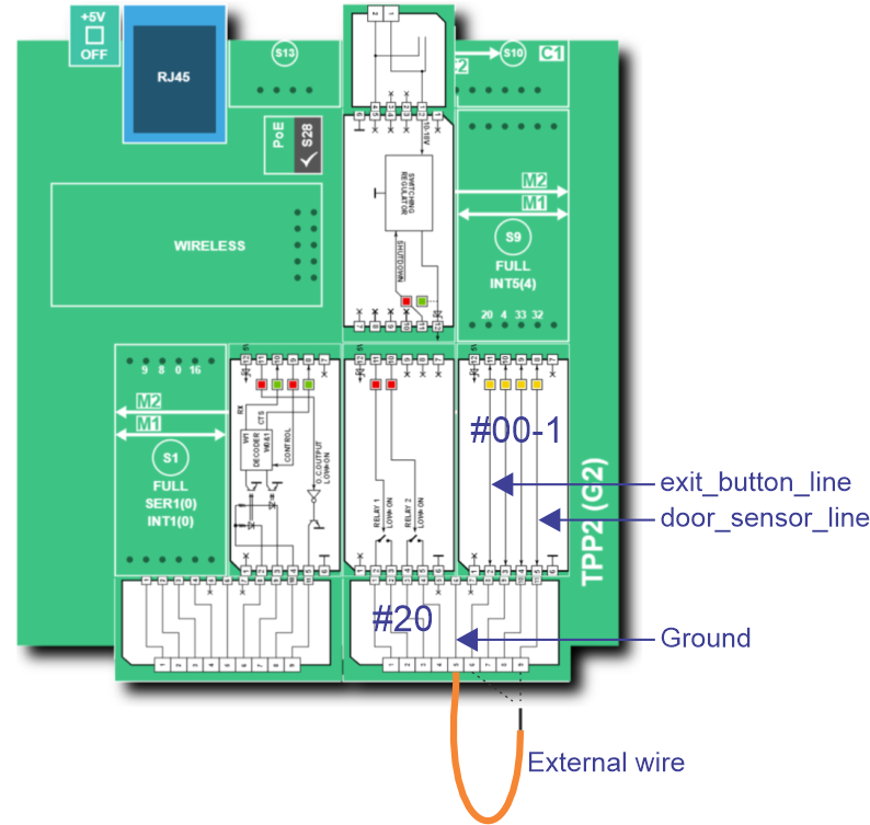
In the AppBlocks Demo Kit (ADK), the four inputs of Tibbit #00-1 are connected to four pushbuttons marked "BTN1~BTN4." BTN1 functions as an exit button. BTN4 stands in for the door open sensor; pressing it is like opening the door.
In real life, door open sensors usually work in reverse -- the switch inside the sensor is closed when the door is closed (this is equivalent to holding the button pressed) and is opened when the door is opened (equivalent to releasing the button). We strayed from this convention to make the testing more convenient.
If you do not have the ADK, you can test the inputs using a piece of wire. First, connect one of its ends to the ground terminal, then touch the exit button and door open sensor inputs with this wire:

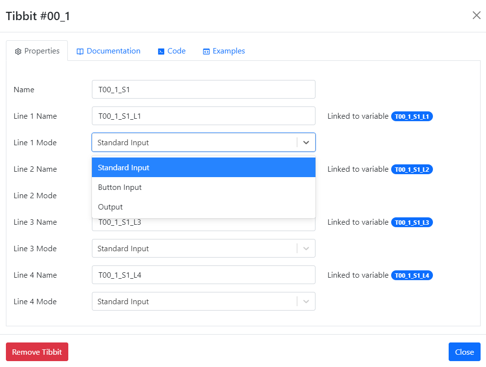
Have you noticed? Each IO line of Tibbit #00-1 can also function as an output. This is because this Tibbit's lines are bidirectional, and it is your job to configure them correctly:
