Distance measurement using ultrasonic sensors is an essential feature of many industrial automation applications requiring level measurement, object detection and counting, proximity sensing, distance measurement, dimension measurement, and much more. This guide walks you through the hardware setup and AppBlocks visual programming to build a fully functional distance meter using a MaxBotix ultrasonic sensor.
System Overview
Use Cases for the Distance Meter
Any application that needs to know the distance between two objects can benefit from using a MaxBotix sensor. Here are a few examples:
- Smart parking sensors
- Liquid level monitoring
- Object proximity alarms
- Garbage bin fill level indicators (know how much trash is present in a container)
- Grain level in silos
- Sonar positioning systems
App Features
Receive readings from a Maxbotix sensor and show them on the LCD.
Hardware
For this guide, we will use the MaxBotix TankSensor MB7851. MaxBotix offers many other sensor versions optimized for different applications. When choosing a sensor, ensure it is designed for your specific use case, as environmental factors such as temperature, humidity, air quality, vibrations, target size, background objects, etc., will all affect its accuracy. MaxBotix's FAQ is a great starting point.
Wiring
Here's the wiring diagram:
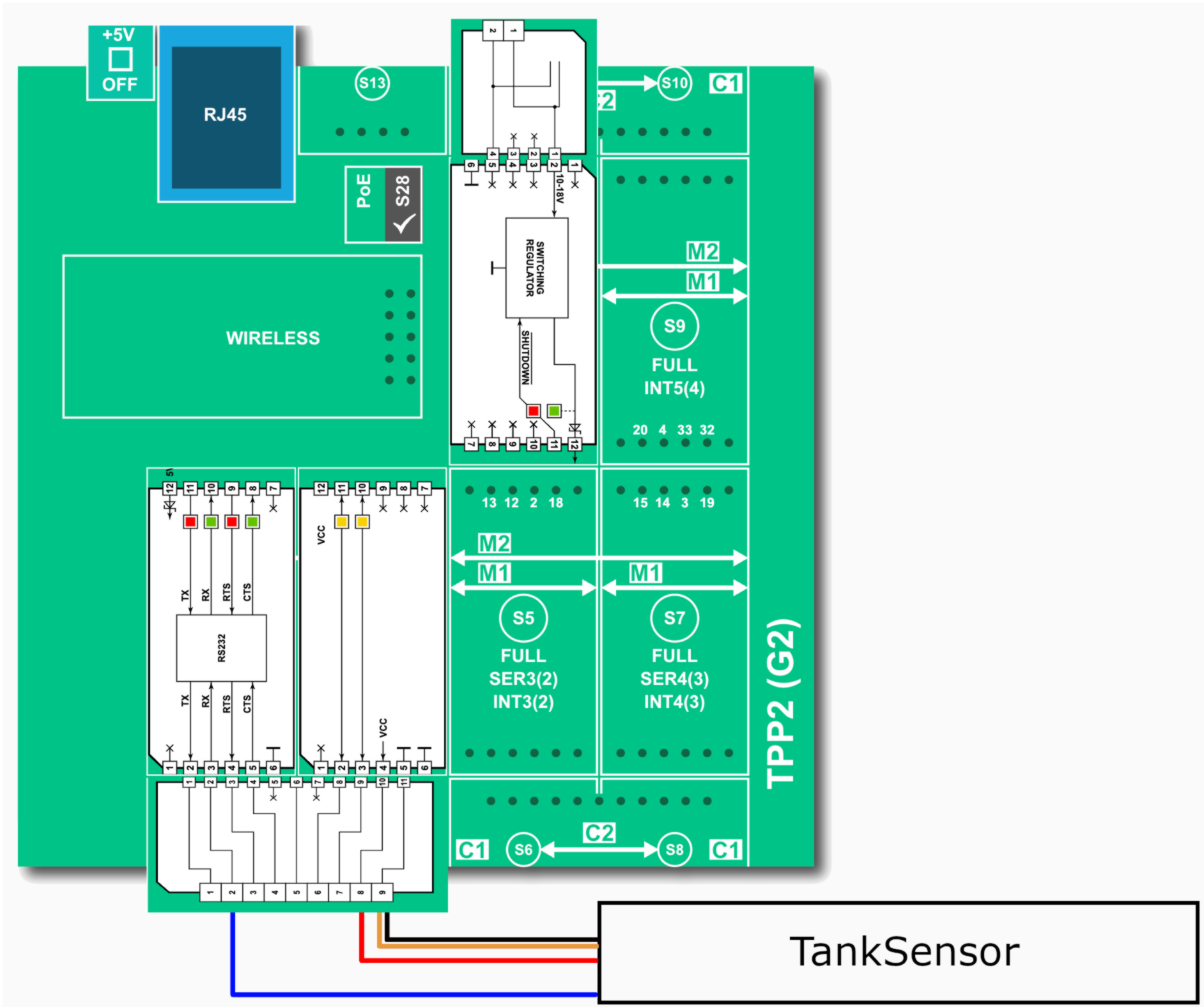
Also, see this article for a more detailed explanation. By default, the sensor is in the TTL serial mode. To switch it into the RS232 mode, connect the orange line (#2, AE) to GND. This is covered in the Serial Communications section of MaxBotix's guide.
DO NOT connect the RS232 Tibbit's TX output to the sensor's RX line. This may cause permanent damage to the sensor.
Logic
With the hardware ready to go, we will now go over the AppBlocks App.
The sensor communicates with the TPS via the serial channel. The readings from the sensor come in the following packet format R#### T###\r, where the #s are digits from 0-9. The first number (the digits after R) is the distance reported by the sensor in millimeters. To read this data, we must configure the "On Serial Data Received" block as follows:
The Packet End input field is actually not empty! There is one space there, which represents the space between the last digit for distance and the 'T'.

The "On Serial Data Received" block passes two parameters to the Variable Set block: data and complete_data. data is what we want in this case, complete_data is used when you want to receive the whole packet.
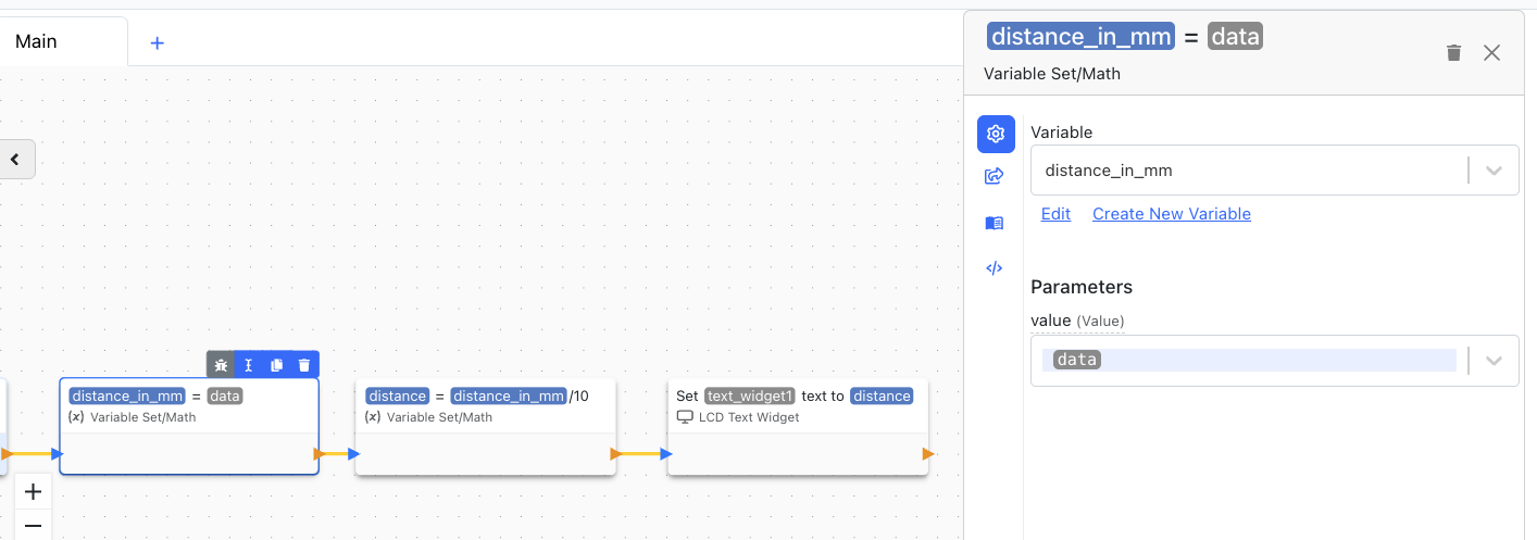
The second "Variable Set" block handles the conversion of data from mm to cm. The last block, 'LCD Text Widget' updates the TPS screen.