
41 posts tagged with "tutorial"

View All Tags

Access Control 6: Real Inputs

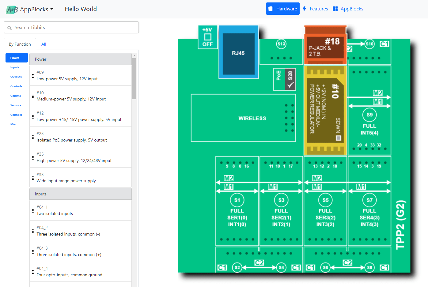
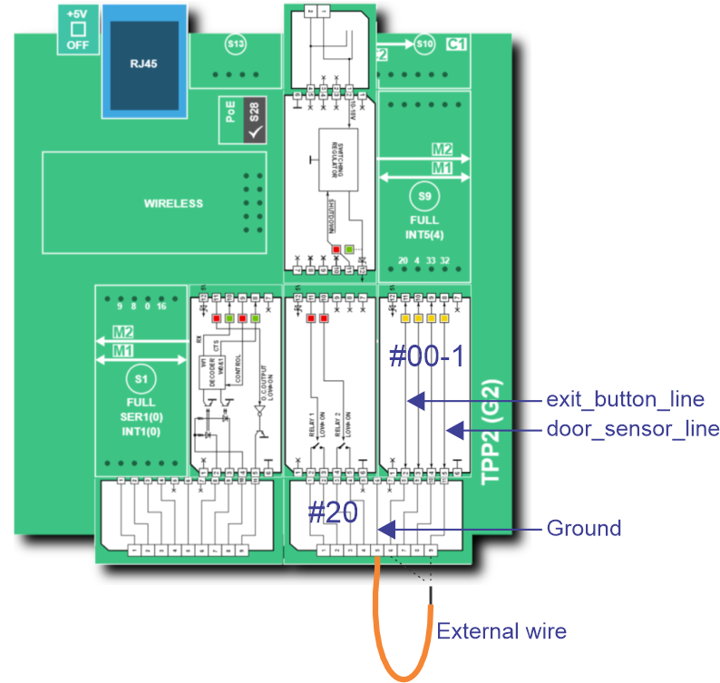
This final step shows you how to work with real inputs. For simplicity, all previous project iterations implemented the exit button and the door open sensor as keypad buttons. This is convenient for testing, but real life requires wiring a real button and an actual sensor to your TPS. In this project's configuration, external inputs are wired in through Tibbit #00-1 (four direct IO lines).

Tibbit #00-1 is very convenient for testing: To switch its inputs from HIGH to LOW, you only need to short them to the ground. Real-life applications are unlikely to use this Tibbit as it offers no protection against noise or excessive voltages. Tibbits #04-X (optically isolated inputs) and #54 (four optically isolated dry contact inputs) are much better candidates for the job... but this is a demo, so #00-1 will do just fine.
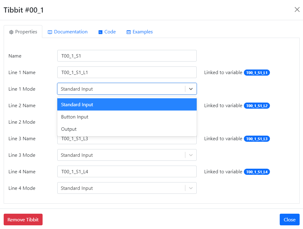
Three Input Modes

There are three input modes for a TPS IO line: a standard input mode, a button input mode, and an interrupt input mode. The following table details the differences between the three:

Input ModeDetailsLimitationsRelated Event BlocksFiltering LOW and HIGH Transitions
StandardPolled at one-second intervalsSlowOn Variable ChangedApplication's job
ButtonPolled 100 times/per second, with debouncingOnly up to 8 inputs* can be designated as button inputsOn Keypad Pressed,
On Keypad Released
Separate events for LOW and HIGH transitions
InterruptUses hardware interruptsOnly the fourth IO line of certain slots can be used as an interruptOn Variable ChangedConfigurable

* The number drops to 4 if you enable the LCD and keypad of the TPS2L system.

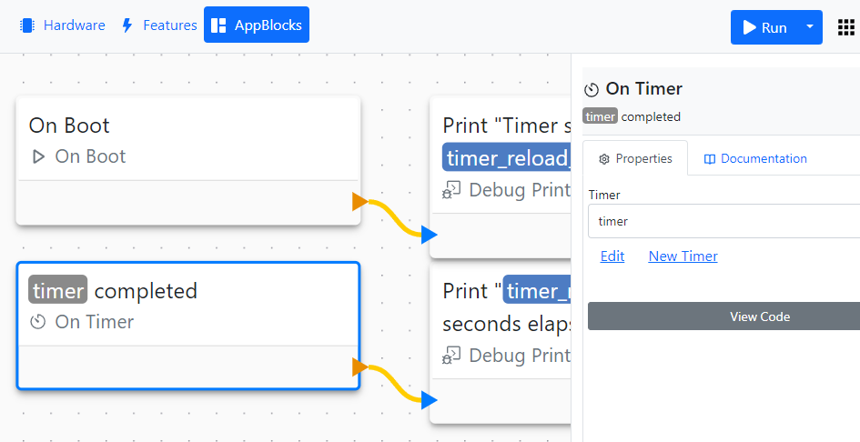
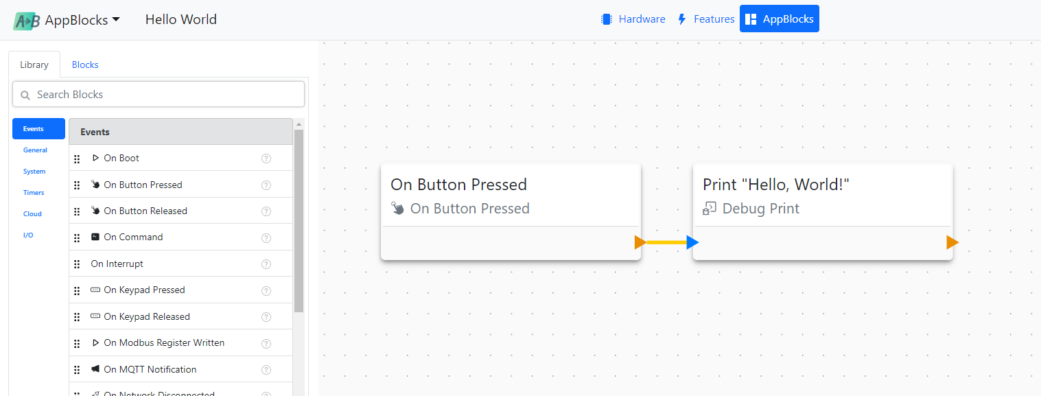
Now that you know what choices are available, you can appreciate the ones we made for this application. Predictably, the exit button line is operated as a button. The door open sensor line is configured as an interrupt. This ensures a fast reaction to any changes in the sensor state. The corresponding event block is called On Interrupt. This is the first use of the block in these Tutorials.

Testing the Inputs

In the AppBlocks Demo Kit (ADK), the four inputs of Tibbit #00-1 are connected to four pushbuttons marked "BTN1~BTN4." BTN1 functions as an exit button. BTN4 stands in for the door open sensor; pressing it is like opening the door.

In real life, door open sensors usually work in reverse -- the switch inside the sensor is closed when the door is closed (this is equivalent to holding the button pressed) and is opened when the door is opened (equivalent to releasing the button). We strayed from this convention to make the testing more convenient.

If you do not have the ADK, you can test the inputs using a piece of wire. First, connect one of its ends to the ground terminal, then touch the exit button and door open sensor inputs with this wire:

xxx

Have you noticed? Each IO line of Tibbit #00-1 can also function as an output. This is because this Tibbit's lines are bidirectional, and it is your job to configure them correctly:

accesscontrol6

Scheduler

You already know that periodic actions can be implemented using Periodic Timers. For actions that must happen periodically but do not necessarily fit into a simple "every X seconds" pattern, the Scheduler may be used. Schedules are configured on the Scheduler page of the Features tab. The corresponding event block is called On Scheduled Event.

Scheduler configurations may be as simple as "do X every minute" or as sophisticated as "do X only on Mondays and Tuesdays of June, at 6 pm."

scheduler

This project demonstrates the simplest example: Once a minute, the application will read the current date and time using the Get Current DateTime block (first use in this Tutorial), then Debug Print it into the console window.

At first, using the scheduler in such a simple project may seem unwarranted -- why not use a simple Periodic Timer instead? There is, however, a crucial difference here. The Periodic Timer may be set to execute something every minute, but you can't force it to trigger precisely on the minute.

Sometimes this doesn't matter, and then using a timer is OK. Other times, you'd want to trigger something as soon as the new minute starts! For example, this project prints the time as it progresses, so it is only natural that the time update would be synchronized with the clock.

Parameter Passing

There is an additional trick that you learn with this project -- parameter passing from one block to another. Look at the project's flowchart. The current time and date are obtained using Get Current DateTime. The date and time are then printed by the DebugPrint block. How did the date and time get from one block to another? There are no variable assignments here!

The answer is that the date and time are passed as a parameter. In situations where one block outputs a value, and then the next block has the ability to consume this value, direct parameter passing becomes possible. In this project's case, the parameter name is time_now. Click on the DebugPrint block to see this parameter specified in the printstring.

scheduler

Adding schedules to your project automatically enables the SNTP protocol (see the SNTP page of the Features tab). This is because executing schedules requires the device to know the current date and time. This is where the time zone also comes into play for the first time. For your schedules to work correctly, configure the Time Zone property on the General page of the Features tab. Designing for a global audience? Link the Time Zone property to a setting, expose it through the web or LUIS interface, and let your users make the selection.

Settings

This project introduces a new storage type -- settings. Settings are kept in your device's EEPROM. They are referred to as "persistent storage" because they retain their values even when the device is powered off. Settings are incredibly important, as they provide a way to store your application's operating parameters.

This project builds on the Timers application. It uses a single setting to store the reload value for a (one-shot) timer.

Settings are defined on the Settings page of the Features tab:

settings_timer

Every time you add a setting, a corresponding variable of the same name is created. This is very similar to (one-shot) timers, which also have corresponding variables.

settings_timer_2

Settings have the same list of types available to them as variables. You can directly use settings in math expressions, just as you would use regular variables. You will notice that in addition to all the properties variables have, settings of certain types can also be limited in the value range:

settings_timer_3

Since the settings are stored in the EEPROM, and EEPROMs have the maximum number of write cycles they can endure, avoid designs that constantly rewrite the setting data. Depleting an EEPROM IC is not as impossible as one might think!

Since settings store your application's operating parameters, it is usually necessary to access them "from the outside." This project facilitates editing its setting through the device's web interface.

The web interface is enabled through the Web Dashboard page of the Features tab. Inside the Web Dashboard, there is a Settings sub-page. Every setting that needs to be exposed through the web interface must be manually added there. Since this application only has a single setting, it is this one setting that has been added to the Settings sub-page of the General group.

settings_dashboard

Once you add anything to the Web Dashboard, the Web (HTTP) Server is also automatically enabled.

Accessing the Web Interface

To access the web pages of your TPS, you will need to assign a valid IP address to it first. This is where the Ethernet page of the Features tab comes into play. The DHCP property is set to Enabled by default. Your TPS device will get a valid IP address from the DHCP server, but how will you know what this IP address is?

The simplest way is to use the Device Explorer:

settings_device_explorer

Open it after the application is uploaded onto the device and starts running. Click Refresh to make sure you are looking at the latest data. The Device Explorer can be accessed at any time by pressing this button in the bottom left corner of the page:

settings_device_explorer_icon

Note the IP of your device, and point your browser to this IP. Voila, you have access to your application's lone setting:

settings_dhcp

Responding to Setting Value Changes

There is still one last trick to show you in this project: Responding to setting (variable) value changes. The On Variable Changed event block triggers every time the corresponding variable changes its value. In this application, changing the setting value will cause a debug message to be printed.

You can use the On Variable Changed block to report value changes for plain variables and settings but not for timers.

Setting Initialization

As you already know, settings are stored in the EEPROM. They are used to keep the operating parameters of your application. Settings retain their values even if your device is powered down or rebooted. Thus, there is no such thing as routinely initializing the settings at boot -- something that always happens to regular variables.

So, when do settings get initialized (restored to their defaults)? Ordinarily, this happens only when the user chooses to do so.

There are several methods of initializing settings. One way is to use the Initialize Settings button on the web interface page.

settingsinit_web

Another way is to offer your users a "button-based" way to cause a setting init. This application shows how the TPS' MD button could be used to trigger the setting init safely. "Safe" here means that the procedure is intricate enough that it is unlikely to happen by accident.

Your TPS' MD button was introduced in the Hello, World project.

Here is how the initialization process is triggered:

  • Press and hold the MD button for at least five seconds. The green status LED will be on during this time.
  • Once the 5-second interval elapses, both green and red status LEDs turn on, and the Initialize Settings block is executed.
  • After the initialization, the green status LED starts blinking fast.
  • Releases the MD button -- the On Button Released event block is called. If the setting init has already happened, the Reboot block will execute.
  • If you release the MD button before the 5-second interval expires, the process is aborted and has to be restarted.

Apart from demonstrating a suitable setting initialization sequence, this project also showcases the use of (one-shot) timers, On Button Pressed and On Button Released events, device rebooting with the Reboot block, as well as various LED patterns.

There is a condition when the settings are initialized automatically. It happens after the so-called "schema change." A schema change occurs when you run an application on a device, then edit the list and properties of settings, and upload the application to run again. At this point, the layout of data stored in the EEPROM may not match the updated "setting schema." After the schema change, your application will check the validity of each setting at boot. Any settings found to be invalid will be initialized to their default factory values. Valid settings will be left untouched.

Timers

This application introduces timers. When a timer is preloaded with a value greater than zero, it counts down at the rate of one count per second. Once the timer reaches zero, it generates an event.

In this application, a timer event causes the timer to be reloaded with the same value, causing it to count down again, and so on.

Times are defined on the Timers page of the Features tab:

timer

Adding a timer automatically creates a variable of the same name.

The type of such timer-linked variables is a dword, which is a 32-bit integer value. In Variables and Arithmetic, we already explained that variable types other than the four types explicitly available to the user exist in "certain parts" of the system. This is one such case. You cannot directly declare a variable of the dword type, but you can create a timer, which will be assigned the dword type automatically.

timer_variable

You can use timer variables anywhere in the application, just as you would use plain variables. The only difference is that when a timer runs, its value automatically decrements with each passing second until it hits zero. Once a timer reaches zero, the On Timer event is generated. This application relies on this event to reload the timer.

Your application may have multiple timers and multiple On Timer event blocks. The properties sheet of the On Timer block allows you to select which timer this block belongs to. However, It is impossible to have multiple On Timer blocks for the same timer.

timer_block

This kind of timer is often referred to as a one-shot timer. It is thus called because the timer stops once the countdown reaches zero. AppBlocks also has periodic timers -- introduced later in this Tutorial -- that keep auto-reloading with the same initial value.

Back to the application now. So, every time the timer expires, it is reloaded by the value stored in the timer_reload_value variable... but where does that variable get its value? The answer: Each variable has a default value property. You can edit default values on the Variables page of the Features tab:

timer_variable_default_value

Periodic Timers

AppBlocks has another type of timer called a periodic timer. Unlike the plain (one-shot) timers discussed in the previous topics, periodic timers:

  • Are configured at design time and cannot be reloaded at run time
  • Are always running (cannot be stopped)
  • Cannot be restarted
  • Auto-reload and start counting down again as soon as they reach zero

Periodic timers are implemented as On Time Period event blocks. To configure the timer period, drag the On Time Period block onto the canvas, click on it, and set the desired period in the block's property sheet:

periodic_timers_1

Here is a simple project with two periodic timers, one programmed for a 5-second interval and another one -- for a 7-second interval.

The project also introduces two new useful blocks: LED Pattern and Buzzer Pattern. Every time a 5-second timer expires, an LED pattern will "play" on your TPS' red and green status LEDs. Every time a 7-second timer expires, your TPS will beep a buzzer pattern. Again, the patterns for the LED Pattern and Buzzer Pattern blocks are set on the blocks' property sheets:

periodic_timers_2

LED Pattern Format

The pattern used in this application -- "G-R-B" -- means:

  • Beat 1: Green status LED is on
  • Beat 2: No LEDs are on
  • Beat 3: Red status LED is on
  • Beat 4: No LEDs are on
  • Beat 5: Both green and red status LEDs are on

So, G, R, B, and - are like beats in a melody -- each beat is allocated the same standard time. Your pattern may include up to 16 beats.

There are also two modifiers:

  • Adding * anywhere in the pattern makes that pattern play twice as fast. You can add up to three * characters to achieve the x8 pattern speed.
  • Adding ~ anywhere in the pattern will make this pattern loop, i.e., play repeatedly, until another pattern is loaded (using another LED Pattern block).

Buzzer Pattern Format

Your beats may include the following:

  • B for "beep," and
  • - for "silence"

As with the LED patterns, you can add up to three * characters to increase the pattern speed and ~ to make it loop.

Variables and Arithmetic

This project is the first one that "gives you a reason" to open the Features tab. Nested between the Hardware configuration and AppBlocks (dynamic behavior) tabs, the Features tab comprises a collection of pages that define everything that is permanent in your project. Your application's variables are one such entity in the sense that variables are not created and deleted dynamically but exist as a static list.

To add, delete, or edit the list of variables, turn to the Variables page of the Features tab:

variable

AppBlocks supports four fundamental variable types:

  • Numerical (single-precision floating point), a.k.a. a "value" or a "number" type
  • String (up to 253 single-byte characters)
  • Date Time (1-second resolution)
  • Date

A few other variable types exist elsewhere in the system, but only these four are explicitly available.

Once you have at least one numerical variable, you can perform arithmetic operations on this variable using the Arithmetic block. In this simple application, the value of the Counter variable is incremented and printed to the console every time you press the MD button. To see or edit the block's contents, click on the block to open its properties:

arithmetic

The MD button was introduced in the Hello, World project.

Hello, World

Welcome to your first AppBlocks lesson. Naturally, this is the "Hello, World" of AppBlocks.

Each AppBlocks project is presented on three tabs -- Hardware, Features, and AppBlocks.

The TPS configuration is defined on the Hardware Tab. To add Tibbits to the configuration, drag them onto the desired socket or click on the socket and select from the list of Tibbits available for that socket. Only a power supply and a power jack Tibbits will be needed for this simple project.

helloworld_hardware

The AppBlocks tab shows the application flow as a block diagram. Blocks are added by dragging them from the left panel onto the application canvas. The flows proceed left-to-right and always start with an event block, in this case, the On Button Pressed event.

helloworld_appblocks

The "button" that causes the On Button Pressed event block to trigger is the MD button of your TPS device. Here is where the button is (and the button above it is Reset):

helloworld_appblocks

To run the application in debug mode, click the Run button at the top right corner of the screen:

helloworld_appblocks

In the debug mode, your application executes under AppBlock's supervision. There is also a release mode (often referred to as the "production mode"), in which the device runs unattended. You can only run this particular application in the debug mode because it uses the Debug Print block. Messages generated with Debug Print are shown in the **Debug Panel"", which is only available in the debug mode.

As soon as you click Run, a Device Explorer dialog will open -- you have to find your TPS device on your LAN and select it as the debug target.

Device discovery is performed by a small executable file that needs to be installed on your PC. You will be offered to do so the first time you click Run.

Once the application is running, press the MD button on your TPS. This will send the "Hello, World" message to the debug console:

helloworld_debug

Congratulations, you've just completed your first AppBlocks lesson!

Date & Time Formatting

This project takes the previous application -- Scheduler -- and adds a date and time formatting step. This is achieved through the use of the DateTime Formatter. Click on this block to see all formatting options.